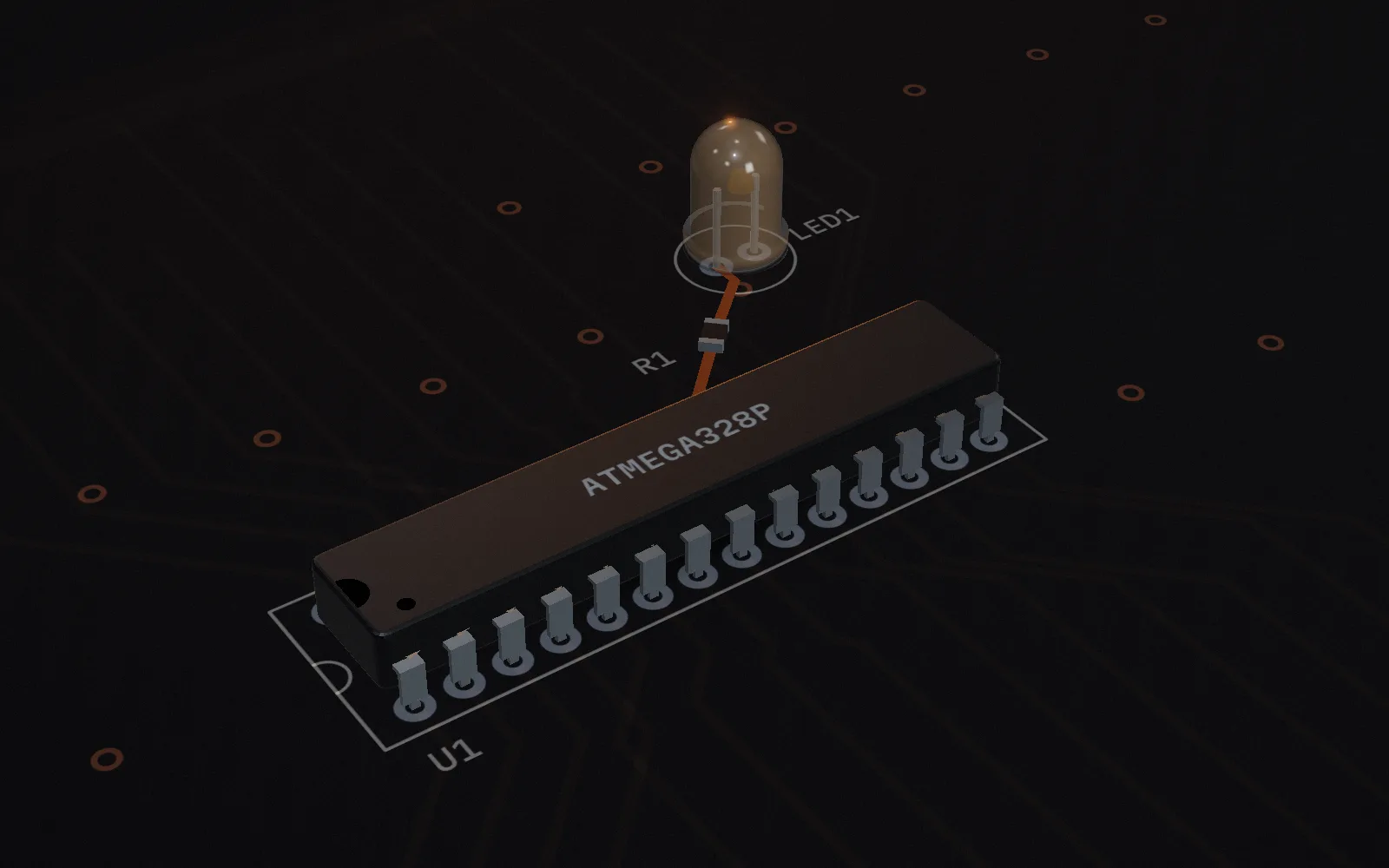
1. The board from above: the ATmega328P, a resistor, and an LED that is not lit yet.

    One command, three layers

    Each lesson teaches an UNO R3 idea twice: the Arduino call first, then the register-⁠level C underneath. Scroll to follow one line down into the chip.

    digitalWrite(13, HIGH);

    This line sets pin 13 to 5 V1. On the UNO R3, pin 13 is the pin with the built-⁠in LED2.

    Start Lesson 1

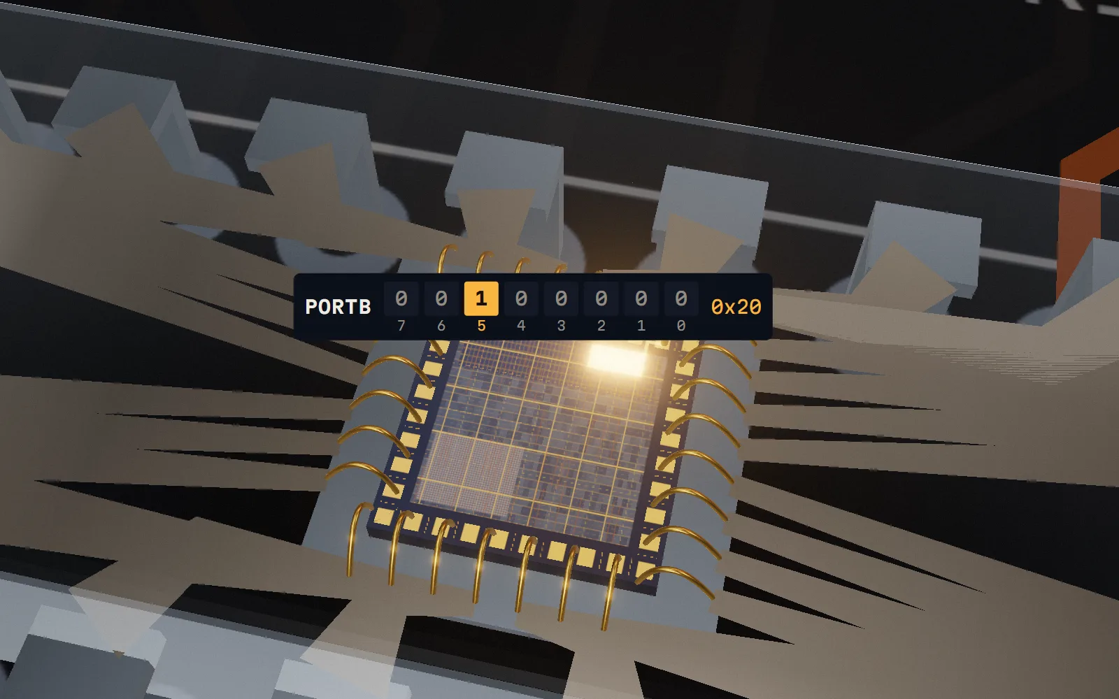
  2. Inside the translucent package: the silicon die, gold bond wires, and eight register tiles with bit 5 lit.

    The register write

    PORTB |= (1 << PORTB5);

    Pin 13 is bit 5 of the PORTB register2, so setting that one bit does the same job. PORTB is eight bits wide3; this line changes only bit 5.

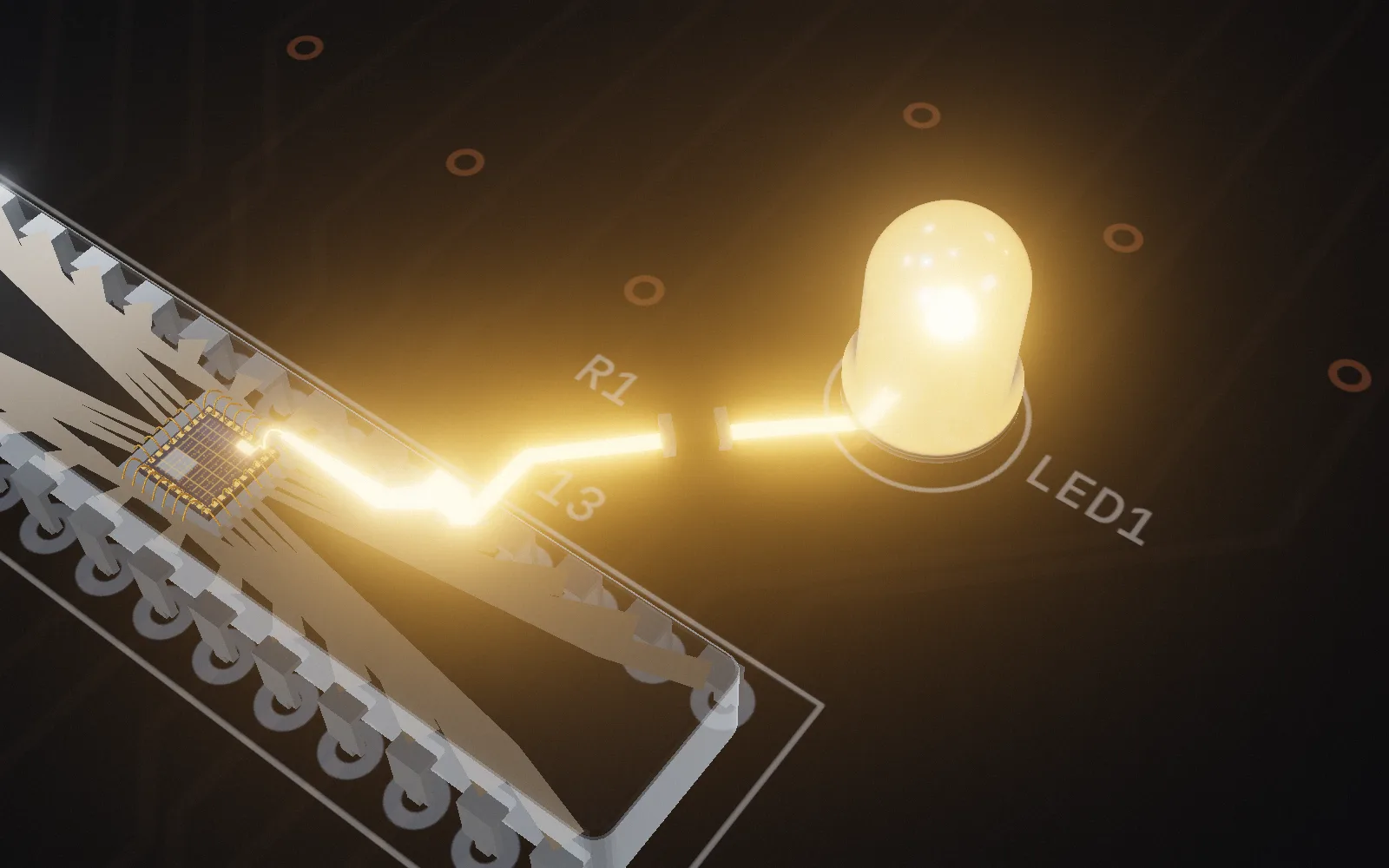
  3. Behind the chip: pin 19 and the copper trace to the LED, lit along its length.

    The pin

    PORTB bit 5 is physical pin 19 of the ATmega328P’s 28-⁠pin package3. Set the bit and pin 13 sits at 5 V; clear it and the pin sits at 0 V1. Lesson 1’s sketch does both, a second apart4:

    Pin 13 voltage while the Lesson 1 sketch runs5 V for 1000 ms, then 0 V for 1000 ms, repeating.0 s1 s2 s3 s4 s5 V0 V
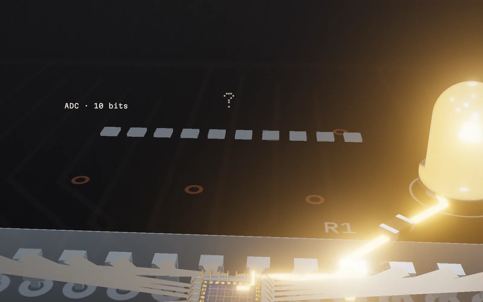
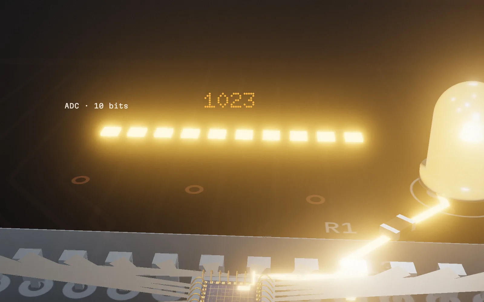
  4. Above the chip: a row of ten unlit tiles, the ten bits of the ADC, under a question mark.Above the chip: a row of ten lit tiles, the ten bits of the ADC, reading 1023.

    A question

    What’s the largest number analogRead() returns on an UNO R3?

    Show the answer

    1023 The reading runs from 0 to 10235: ten bits, all set. In one sophomore mechanical-⁠engineering course, the most common answer was 2556, which is the top of analogWrite()'s range7.

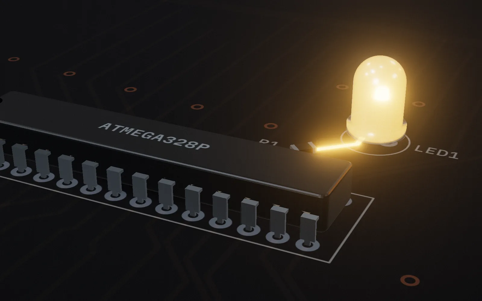
  5. The finished board with the LED lit.

    Start with the LED

    Lesson 1 blinks pin 13 twice: once with digitalWrite, once through DDRB and PORTB. Then you run both versions in a browser lab that executes the compiled program.

    Start Lesson 1See the course map

Course map

Three lessons are written. The next two modules are planned and not written yet.

  1. Digital pinsLesson 1
  2. Analog input and sensorsLesson 2
  3. PWM and motorsLesson 3
  4. Timers and interruptsNot written yet
  5. Serial buses: UART, I2C, SPINot written yet

Sources

  1. Arduino reference: digitalWrite: HIGH sets an output pin to 5 V on 5 V boards
  2. ArduinoCore-⁠avr, variants/standard/pins_arduino.h: LED_BUILTIN is 13; pin 13 is PB5
  3. Microchip ATmega328P datasheet DS40002061A: 28-⁠pin PDIP pinout (p12); PORTB (p100)
  4. Arduino reference: delay
  5. Arduino reference: analogRead
  6. Bedillion & Muci-Küchler, ASEE 2018: SDSM&T ME-265, 25 students
  7. Arduino reference: analogWrite: values 0 to 255